Friday 28 October 2011

GROUP PROJECT - ROUGH STORYBOARD IDEAS

These are our initial storyboard idea drawings.

They are very rough, but a platform to develop our ideas further.

Once we have reached a final decision on our direction, I will draw these up in more detail.

Currently, we are considering taking elements from both of these ideas to use in our final animation.

Idea 1:


Idea 2:


(I will re-draw these later and colour in black pen - as they scans haven't been very flattering.)

Slightly Refined Idea: (Still Rough)


Friday 21 October 2011

One for the Road ....

In the limited time I had available today I managed to add a bit of skin to my model.

My Model Progress at this stage is highlighted below:


Model with a little skin:


Close Up:


Head Model:

Thursday 20 October 2011

Reflection so far...

The progress I have made so far within this modelling process has been quite satisfying. I initially felt that I would struggle creating my head model. Even though it has taken me a lot more time than I would have expected to get to the stage that I have reached. I am very pleased with my actual head model so far.

I believe the model is a fairly good representation of my face and I feel a sense of achievement in respects to the creative work.

I am basing this blog post on my progress so far, there is a little more time today before the hand in, during which I will attempt to develop my model a little further and time depending hopefully I may be able to put at least some skin on my model.


I feel I have rushed the uv mapping slightly. Given more time I would have like to have given more energy to this stage attempting to eliminate a little more stretching. I also would like to spend more time on my ear generally. Perhaps a little more detail and again a bit more attention to the mapping could improve my model further.

Obviously, skin, hair and exploring the texturing further are all elements that I would like to conquer before the final deadline.


My Head:


Tuesday 18 October 2011

Phase 6

UV Mapping:

To commence mapping I selected editable poly in the modifier selection and turned off symmetry so that I would be working with my original R side of my face.

The unwrap UVW modifier was added and the sub selection tool face selected. I made my L viewport full screen so that it was clearer for me to work on.

Paint selection was used to paint the entire face excluding the ear, clicking and dragging the "spray can" over the face surface.


Preparation:


When the entire face was fully painted I moved down to the map parameters. In the sub object selection "cylindrical" was selected and I ticked align-z to align the face. Using the scale tool the cylinder was modified to surround the entire head and centre it within, also trying to make sure there were no green seams other than down the centre of the head and around my ears.

I opened the material editor (m) and applied a "checker" pattern by selecting (button beside) diffuse and chose "checker" and hit the 'show map in viewport' button so we would see the applied material.

I checked my face to see how the structure of the squares looked as squares can show off any stretching a little easier.

Still in the UV parameters panel I selected 'edit' which opened a new window which showed my face and ear outline mapped out on a grid. Here I began to sort out any stretching.

Before I started I ensured constant update was selected so I could see the changes I made in real time and made sure the map wasn't inverted and fit nicely within the grid.


I started working my way from the top of my head as it was a key problem area for stretched quads. To rectify this I highlighted all vertices near the affected area and using 'relax' selected relax by edge angles which rounded the top of the head off a bit more effectively.

I repeated this process on all other trouble areas on my map until I had a nicely flattened out outline of the head.

Another key problem area was my neck as there were many overlapping lines. To fix this I had to use paint selection again to flatten out the neck area, dragging paint all over the vertices in that region. Here though, instead of using relax by edges like the majority of the face I used 'relax by centres' which helped make the checker pattern more uniform .

Face Map:


I felt I tried my best here, though I was aware that I had to hand in my model. In an ideal world I would have liked to have spent a little more time over this process ensuring that there was no stretching whatsoever, unfortunately at this stage there still is a little on the top of my head and neck area. Possibly my lips also could require a little more attention.


Ear:

Mapping the ear follows pretty much the same procedure as the head.

In material mode I turned off the checker material. In map parameters 'planar' was selected this time instead of 'cylindrical' (above). The planar shape was dragged over the ear area, align-x and 'fit', so it was secure around the ear.


Within Pelt mapping dialogue box the outer ring of the ear was selected, pulled out, rotated and flattened. Using the point to point tool I created a break seam to flatten out the rest of the ear.


I closed the edit and applied the material again on the model. Within the normal map edit mode the ear was scaled down and attached to the grid along with the head. I turned on symmetry and applied a second unwrap uvw modifier on top of symmetry. I ensured that I selected the left face and mirrored it, lined the two sides up along the centre so that I had a full face again, albeit a little stretched.

All the vertices along the centre line were welded together and selected the left ear and it was dragged to the opposite side again mirroring the original placing.


UVW Symmetry:


Mapped Head:


The mesh was then formatted into an image to use in photoshop using the render uvw template.


Versions were also rendered using normal and shaded options.

Normal UV Map:


Shaded UV Map:

Phase 5

Head and Neck:

So, now that the model of my face is coming along reasonably nicely. It's time to think about the rest of the head.

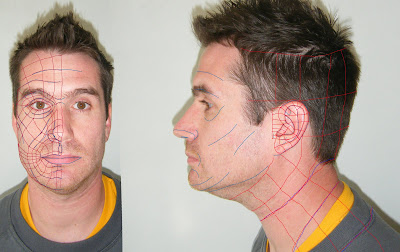
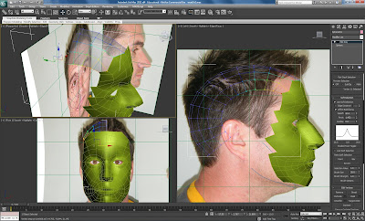
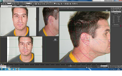
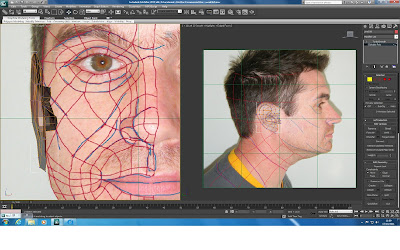
Firstly, I needed to go back to photoshop and create my topology lines on the side of my face, to draw topology on my ear and run the lines off down to my shoulders. The new modified image was then imported as before into 3DS Max as an updated reference.

Revised Topology:


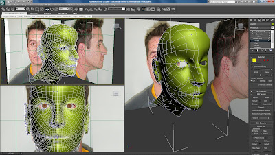
In order to create the head extension a sphere was created from the shapes modifier, rotated 90 degrees, scaled down and roughly positioned over my head. (again alt x can turn on transparency mode to help here)


Sphere added:


Here I tried to match up the lines of the sphere with my topology lines and adapted the sphere to the size and shape of my head. The Paint selection is then used like a little spray can which allows us to remove geometry which will not be needed by holding down ctrl and spraying the can.

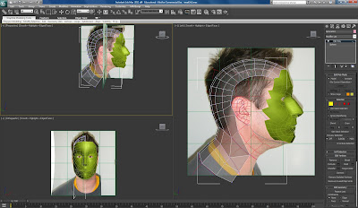
The end result is hopefully a nice curved semi circle at the top of the head.


Soft selection was used on the last vertex to help push the sphere into shape and line it up correctly in preparation to attaching it to the face. It also gives the effect that the lines smoothly taper off the head.


(I didn't actually import my new photoshop file until this point as you will see on further drawings - but method explained above)


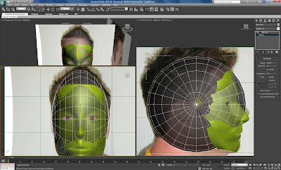
Once I felt that I had lined up the head piece successfully I was ready to attach it to my face again using the snap tool, matching up the vertices of the head with the existing lines on my face. I began to create polygons to make up the rest of my head to replicate the quads on my topology image.

At this stage I discarded the ear momentarily.


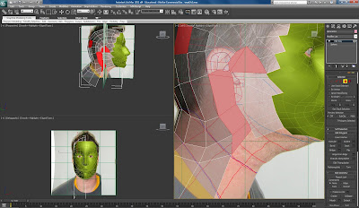
Once happy that my head and neck portion had been created fully, keeping my flow lines accurate and matched up to the lines on my face, it was time to attach the head to the face. This can be done within edit polygon - edit geometry - attach, then welded all the head vertices to the face.

In order to test if all of the vertices had been welded, I just pulled around the points a bit.
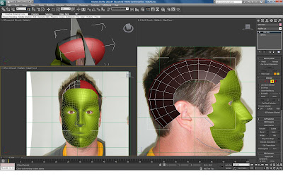
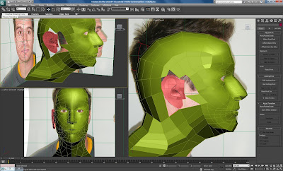
I turned on turbosmooth again to have a look at the detail in my model and amended any slight changes to the vertices if there was any unsmooth areas from attaching the head.

Joining Head:


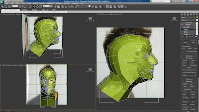
Turbosmooth of Full Head:
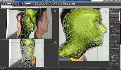


Ear Creation:


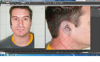
As mentioned above the ear topology was re-drawn and updated in 3Ds max as a reference.

During the head creation I left a space to accommodate the ear. The ear was created using the same method as the head, starting from scratch using the line tool drawing my quads.
Once my ear had been drawn into 3Ds it was converted into an editable poly, attached and positioned in relation to the reference plane. The individual vertex points were stretched and manipulated to match the ear.


Ear Spline Creation:


Ear Converted to Poly:


For the more detailed areas within the ear; the ear canal and the ridges, edge selection was used to select parts and the chamfer technique was used to create indented portions and depth.

The vertices were moved around again to match the topology of the ear and I found it helpful while doing so to turn on turbosmooth periodically to see the development of the ear.

More Detail:


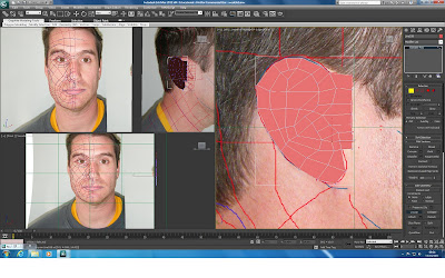
Once I was satisfied with the general depth and structure of my ear it was ready to think about attaching it. In order to do so, a select few polygons were removed from the head section where the ear would go.

So, the ear was selected and set into isolation mode using (alt+q), using the edge tool I selected the back edges of the ear using loop and made it thicker by holding shift, to imitate the thickness from the reference.

I then attempted to simplify the edges on the ear, creating polygons behind the ear to match up with the lines on the head, used vertex mode and the snap tool to move the vertices and dragged the points matching them up, clicking on the head attaching and welding to the ear to ensure that the ear becomes part of the head.

Ear Ready to Attach:


My Head:

Phase 4

Modelling:

Symmetry:

So far I have only been working on the Left side of my face. Once happy with the definition and smoothness of the model so far I began considering the other half of the face.

Thankfully this can be achieved reasonably simply in 3DS Max by applying 'symmetry' in the modifier panel . I ticked flip to flip the face and clicked the plusses by symmetry and mirror which allowed movement of the new side of the face.

I carefully lined up the two sides of the face right in the centre ensuring not to overlap at all, attempting to keep it aligned and make sure all of the curves and edges were still as smooth as possible.

Symmetry Images:


Smoothing & Refining:

Now I started to look at my mesh with the turbosmooth modifier applied which helps give the contrast of your mesh as a completely smoothed out object and adds subdivision.

It is a good gauge to use toggle on and off while refining the finer detail in your model.

So, my face was in reasonably good shape. I moved around the vertices a bit more after the face had been smoothed just to iron out any visible lumps, or curves that needed to be sorted out.

This is where more detail and time is needed to be taken over the more intricate areas of the face. The nose, lips and eyes.

The nose took me quite a long time to get right.

I selected edge mode within the editable poly preferences to select the outer edges of the nostrils, held shift and dragged out more edges building up the nostril area. I used weld to connect to the new vertices the edge of the nose. I selected the vertical edge around the nostril and used connect edges to create a new set of segments. I deleted the edge which was near ther tip of my nose and used the cut tool to join the new segments vertex to the tip of the nose. Toggling between vertex and edge mode allowing me to space them out nicely.

The nostril was achieved by creating a polygon and extruding it inwards, modifying the height to create a cavity.

Again, building up my nose while attempting to keep a nice flow in the vertices.

Nose:


Nostrils:


The lips and eyes were modified in the same manner. Using the same technique as above creating edges and moving them into place keeping an eye on the front viewport to create the shapes, while spacing them out correctly in the left viewport.

Lips:


Eye:


Turbosmoothed at end of this stage:

Phase 3

Modelling:

Adding Depth and Volume:

In this step of the process we begin to create a 3D object from our surface.


Essentially what is done here is that all the vertices are dragged out in correspondance to where they should be on my side image.

We are trying to create an accurate model and it is quite important to try and follow the topology flow while trying to recreate our face.

I began this process by selecting the whole line of vertices closest to the center of my face. Then began to pull out the vertices using the x axis in order to attempt to align them with where they should be with respects to the profile image. In essence trying to match up my face.

I found it helped to use transparency (alt+x) to make it a little easier to see what I was doing through this process.


This is quite a long process which requires a little patience in order to get right. I found it a little frustrating, though when I got lost I could just select a single vertex point and find my place again. It was important to try to work from Right to Left trying to keep the flow lines consistent to my reference picture.

Basically this process was repeated, working through all rows until I had pulled out all of the vertices in my face, attempting to create the depth within my surface. Pulling out vertices and matching them up with where they should be on the picture while trying not to overlap lines to keep a smooth feel to our mesh curves and trying to keep consistent with my topolgy.

A lot more care was taken in the trickier areas such as the eye sockets to ensure that I wasn't overlapping shapes.

This process was quite lengthy for me and I had to spend a lot of time flicking between both viewports, zooming in and out of my images ensuring i was keeping my curve structure as close as possible to my topology blueprint.


Some screenshots of this process:


It can be helpful to turn off transparency view to gain a perspective in what your mesh is looking like throughout this process:


Pretty Much There: