Interior Details:
Picture Frames:
A chamfer box was created and scaled to the size of a frame.
It was converted into an editable poly and face mode used to select the front face. the face was scaled down slightly and a bevel was applied scaling the face in a bit while scaling it down to create an outer edge.
The inner rim was created by copying this (shift and move), then in vertex selection pulling the outer edges of the face out to create finer corners and a kind of border effect, while again extruding a slight edge onto it and scaling it slightly smaller than the first frame.
I then combined the 2 items together, to create the structure of my frame.
I made several copies, to create our pictures throughout. Made planes and applied different images of finchingfield (some of our photos and a few selected images) to become our artwork, and added a glass "shiny/see through" effect using 'refraction' in the map modifier in attempt to make it more authentic.
Gallery Rendered:
I have left the frames quite plain and gold currently, though they look quite good, if required the frames could be further detailed or textured, depending on the style we wish to adopt.
Fridge Magnets:
(fridge magnet reference)
With our desire to put a few cheeky hidden items in our guildhall, I created a few magnets quickly for our fridge.
As I began creating splines and snapping the words of Finchingfield to a grid, Richard enlightened me that I could apply the text spline technique and create my style of lettering much more effectively and efficiently.
Here I was able to select the font and write the text of the intended word to create my letters. Arial Rounded was selected at it was very close to the style I wanted for my fridge magnets. I modified the scale and depth until satisfied.
I created a little box to join the dot to the body of the letter 'i' - to give a bit more authenticity and attached the two pieces of 'i'.
I then went through and individually detached the letters, allowing them to be manipulated individually.
I first just coloured the letters separately to see what they would look like:
I began texturing adding specular material in the editor, increasing the specular value a little to soften the letters a bit. I then selected the letters individually and added a colour to them, then copied the specular settings over the different balls in the material editor, changed ID numbers and selected different colours and applied them to varying letters.
I then individually applied a bevel to the front edges of the letters to give a slightly more realistic rounded feel. On a few letters ('n' and 'h') pinching occured in the render when the bevel value was applied so I had to work on the bevel to sort out the pinching in the corners.
Fridge Magnet Render:
I started to play around with a reflection map on the letters, importing an element from the environment it would be in (fridge, cooker) and adding it to the letters to give the effect of the fridge, I'm still playing around with this technique.
New Technique: Text Spline
Monday, 21 November 2011
Tuesday, 15 November 2011
GROUP: Adding Interior Details (part 4)
Interior Details:
Table and Chairs/Candlesticks:
These were models that I had previously made which I adapted slightly. The table and chairs were simply made from boxes and cylinders and attached together. The candlesticks were bevelled cylinders.
(I adapted the model for our group table by extending the table and adding a few more chairs)
Table Render:
Thursday, 10 November 2011
GROUP: Adding Interior Details (part 3)
Interior Details:
Book:
(book reference/texture)
The idea of placing certain items in reference to Finchingfield research within our environment seemed a fun way to create some intricate interior details. Dodie Smith, one of the village's famous authors wrote 101 Dalmatians, so we decided to create a book to place within our world.
A plane was made and material bitmap book cover image (as above) was applied. In the modifier panel the lengths/width segments were changed down to 1 and it was converted to an editable poly.
The UVW mapping modifier was applied (a new technique for me in reference to texturing items). Border selection was selected and 'shift' held to drag out the depth of the book.
The Unwrap UVW modifier was selected, the front was selected and 'planar' in map parameters, choosing 'align y'. Planar was then unselected and 'edit' chosen in the parameters. In the edit UVW window the material image was selected from the drop down box and freeform mode was used to scale the map to match it to the size of the book cover.
The same technique was applied to the sides of the book, but instead of cover material I added white space for the effect of the pages.
Book Render:
Protractor:
One of our main ideas from our storyboards is that we will have a workbench with a blueprint on that we will use as a platform for an animation phase. So we decided to make a few detailed items that would traditionally be used in this environment. (Protractor, ruler, compass etc..)
A reference plane was created and image applied. As with the book the UVW map modifier was selected and (length/width) were lowered to 1 segment.
The object was converted to an editable poly and vertex selection was used to move the vertices.
Swift loop was used to define the area, then using vertex selection I began to move the vertices to the shape of the image, carefully as not to distort the image.
Once I was happy that the shape of the protractor looked realistic, I applied the turbosmooth modifier to smooth out the corners.
Protractor Render:
To create a more see through effect on the protractor, within the material editor the value of the opacity was lowered, to create a more realistic opaque model.
Lights:
(one of our photographs - used as a light reference)
A Tube was created and converted into an editable poly. Polygon selection was used, all the bottom face selected and extruded outwards.
The scale tool was used to scale all of the edges wider in order to create a lamp shape. Vertex selection was selected and some of the bottom vertices were pulled out attempting to create a the bottom of the shade, matching it up to the reference plane.
A tube was created and scaled down to create a thin mount bar for the light and was attached to the shade.
The Material ID within the modify was set to 1 (whole lamp selected). Swift loop was used to add a new set of vertical edges in order to create the lead lines.
Polygon mode was selected to highlight the gradient sections of the light shade, then within the material editor 'multi/sub-object' was chosen to make varying colours of glass by selecting 'Refraction' within map parameters and applying a 'raytrace' map to attempt to create a "see through" effect. The amount was decreased slightly to allow the colour to show through attempting to keep a nice balance; not too opaque while keeping definition.
The Lead effect (done in the same way as above) but instead of refraction, the reflection map was used and the amount lowered to remove the shine a bit. These materials were then applied to the selected parts of the light and mount bar.
Light Render:
New Techniques: UVW Mapping (Texturing Items)
Saturday, 5 November 2011
GROUP: Interior Models (part 2)
Interior Models:
Kitchen Items:
Cabinets:
To create a simple kitchen cabinet a rectangular box was created and a ring was placed two thirds of the way down it to create a split that I then extruded outwards using face selection to create an L shape.
Another box was created to make the door, scaled to size and depth and copied twice ('shift' and move). The same was done for three door handles though they were created as spheres as opposed to boxes.
Once all the items were positioned in place they were attached.
Polygon selection was used to select the whole model. The ID's of the cabinets were set to 1, then the surfaces were selected and the ID reset to 2. The material editor was opened and within multi/sub-object, the number was set to 2 (to define 2 ID's). ID1 was made using the bitmap of the wood material and ID2 was made using a bitmap of a black granite worktop. Some of the materials were stretched, so unwrap uvw was applied to solve these problems.
Cabinet Render:
Sink Cabinet:
In order to create a cabinet sink, I was able to use my cabinet above.
Swift loop was used to mark out the position that the sink was going to be inserted into. Polygon selection was used to choose the faces of that space. Extrude was then used to extrude the polygons inward to create the depth space for the sink.
My previously made sink was then merged into the environment and positioned within the cabinet.
Sink Cabinet Render:
I realise that I could probably make this item better in terms of adding reflection to the detail, improving the sink, so it looks more like a kitchen sink but really this isn't a significant model in terms of our overall project, merely to add a bit of detail. If there's time at the end I could take a further look at this model, depending on group priorities.
Friday, 4 November 2011
GROUP: Interior Models (part 1)
Creating Interior Models:
Bathroom Items:
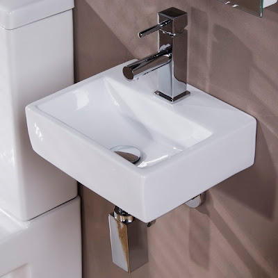
Sink:
In order to begin adding detail to the interior of our guildhall, we needed to create details to make our room more authentic. Items to model were divided up amongst the group.
As often using 3ds max, a reference picture is selected for a basis for your model and imported into 3ds max using a plane.
(sink reference plane)
Sink Creation:
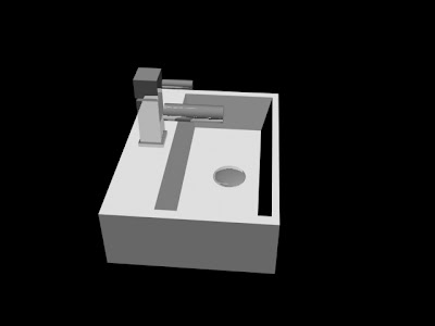
In order to create a sink a box was created. The swift loop was used to create new vertices to define where the inside of the sink would be bevelled (downwards to create the basin space).
The swift loop technique was a method that I had not previously used and has become a very handy technique for further models throughout this project.
A small sphere was also created to act as the drainer/plug detail of the sink.
A similar method was used to create the tap, using swift loop to define the tap area. The faces were selected and the tap detail was extruded upwards to create the shape. The bevel tool was then used to create the partitions/ sections within the tap shape. Two cylinders were created, scaled and attached to make the tap bars.
The whole model was selected and polygon material ID's were applied and set to ID1, the tap was selected and changed the ID to 2 and in the material editor applied multi/sub-object texture and set the number to 2 (to define 2 ID's). ID1 was made white and on ID2 a reflection map (raytrace) was created to illustrate the metallic texture for the tap and drainage plug. The materials were then applied to the models.
Sink Render:
Toilet:
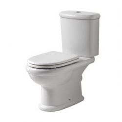
(toilet reference)
Toilet Creation:
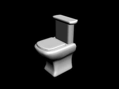
A box was created for the cistern, edge mode was used to select the vertical "inside" edges to manipulate and create a smoother shape. Polygon selection was used to isolate the front centre section of the model. In the polygon smoothing group panel, a different value was selected from the rest of the model, (to generate the effect of smoothing the sides and the face edges together). Turbosmooth was applied from the modifier list and 'smoothing groups' ticked.
This was modified until it looked authentic.
The same technique was used to create the top of the toilet and the seat.
(smooth groups)
A box was created for the bottom section of the toilet. Half the box was deleted in order to apply the symmetry modifier afterwards. The box was converted into an editable poly and vertex selection was used to modify the shape to match it up with the shape of the selected reference image.
Symmetry modifier was applied and mirror axis was selected as 'x' and flip was ticked. The turbosmooth modifier was applied to smooth out the shape.
Toilet Render:
New Techniques: Swift Loop, Smoothing Groups.
Wednesday, 2 November 2011
Subscribe to:
Posts (Atom)